logo
Good price online

products details

Created with Pixso. Home Created with Pixso. Products Created with Pixso.
Twin Screw Extruder Parts
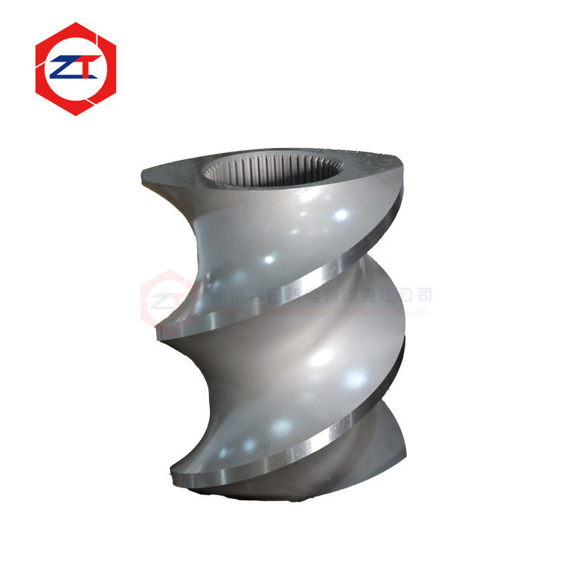
Created with Pixso. Customizable Twin Screw Extruder Elements For Center Diameter 15.6-350mm ZSK 250 Screw Elements

Customizable Twin Screw Extruder Elements For Center Diameter 15.6-350mm ZSK 250 Screw Elements

Brand Name: Zhitian
Model Number: customize
MOQ: 1
Price: Timely quotation
Delivery Time: 5-60 days
Detail Information
Place of Origin:
China
Certification:
iso:9001
Product Name:
Twin Screw Extruder Screw Elements
Compatible Extruder:
ZSK250, Subject To Drawing Confirmation
Extruder Type:
Co-rotating Twin Screw Extruder
Element Types:
Conveying Elements, Kneading Blocks And Mixing Elements
Outside Diameter:
According To Confirmed Component Drawings
Shaft Connection:
Internal Spline According To Confirmed Shaft Specifications
Material Specification:
According To Processing Conditions And Approved Order Requirements
Customization Basis:
Approved Drawings Or Sample Measurement
Packaging Details:
wooden case
Supply Ability:
500 Sets / Month
Highlight:

Customizable Twin Screw Extruder Elements

,

ZSK 250 Screw Elements

,

D350mm Extruder Screw Elements

Product Description

Replacement Screw Elements for ZSK250 Twin Screw Extruders

ZHITIAN supplies independently manufactured replacement screw elements for ZSK250 twin screw extruders. Components can be reviewed for selected-section replacement or a planned screw assembly overhaul, with production based on approved drawings and agreed material requirements.

For a large screw assembly, replacement planning involves more than identifying the machine model. The working profile, internal spline, element length, end faces and installation position must match the intended assembly. Our review focuses on these relationships so that the quotation and production requirements refer to the actual components being replaced.

ZSK twin screw extruder elements

Define the Scope of Your Replacement Project

Start by identifying which elements require replacement and where they sit within the screw configuration. A marked assembly drawing, component list or numbered photograph helps connect each requested part with its installation position.

Useful reference information includes:

  • Machine identification: extruder model, nameplate and available equipment documents.

  • Component identification: drawing number, element marking and quantity.

  • Assembly position: location and orientation within the screw arrangement.

  • Existing condition: photographs of worn profiles, damaged connections or affected end faces.

  • Maintenance objective: selected-element replacement, scheduled overhaul or a proposed configuration change.

This information helps distinguish a repeat replacement order from a project requiring additional measurement or engineering review.

Working Profiles and Element Functions

Conveying elements, kneading blocks and mixing elements perform different functions within the screw arrangement. Replacement geometry should follow the approved configuration unless a process change has been separately reviewed.

For conveying elements, confirm the pitch, conveying direction, overall length and working profile. For kneading blocks, confirm disc geometry, disc arrangement, orientation and total length. Mixing elements require their own profile and installation details.

A component that fits the shaft may still differ in its processing function. Changes to geometry or sequence can affect material transport and mixing, so the replacement specification should identify both the part dimensions and its intended position.

Dimensions That Need Individual Confirmation

The machine designation is a starting reference, rather than a complete dimensional specification. Nominal model information should not be substituted for measured component dimensions.

Feature Details to Confirm
Working profile Outside diameter, profile geometry and relevant clearances
Axial dimensions Overall length, individual section lengths and assembly sequence
Internal spline Spline geometry, fit requirements and engagement length
End faces Contact surfaces, orientation and drawing requirements
Associated components Shaft condition, neighboring elements and barrel wear

Dimensional tolerances should be assigned to the relevant features on the approved drawing. One general tolerance value does not adequately describe every working surface and connection.

Manufacturing from Drawings or Samples

Approved drawings provide the clearest basis for repeat production. Please include revision information and identify any changes from previously supplied parts.

Where drawings are unavailable, samples can support measurement and drawing preparation. However, worn surfaces may no longer represent the original geometry. An unused reference element, shaft drawing or assembly document can help resolve uncertain dimensions.

If a sample has spline damage, worn tips or repaired areas, identify these before measurement. The resulting production drawing should distinguish confirmed geometry from dimensions that still require agreement.

Material Requirements for Large Screw Elements

Material selection should reflect the processed formulation and the observed wear mechanism. Relevant information includes the base resin, filler or reinforcement content, processing temperature and previous service history.

A change of material should be reviewed alongside the component geometry and operating conditions. Hardness alone does not establish suitability, and a material change cannot correct an incompatible spline or an incorrect working clearance.

The agreed order specification should identify the material designation and any required hardness checks or supporting documents. Proposed alternatives should be confirmed before production.

Inspection, Identification and Transport Protection

Inspection requirements are established from the approved drawings and order conditions. Relevant features include the working profile, axial dimensions, internal spline and end-face condition.

For orders containing several element types, agree the identification method before shipment. Component markings and a corresponding packing list can help the receiving team associate parts with the approved assembly sequence.

Large components also require packing that accounts for their weight and contact surfaces. Working profiles, spline openings and end faces should be protected, with components secured against movement during transportation. Packing and shipping arrangements are confirmed for each order.

Frequently Asked Questions

Can only the worn elements be replaced?

Selected replacement may be possible after reviewing the shaft, neighboring elements, barrel condition and existing configuration. Assess these together before deciding the replacement scope.

Is the ZSK250 model name enough for quotation?

It provides a useful reference, but drawings, part identification and connection details are needed to define the requested components accurately.

Can a worn sample be used for manufacturing?

Yes, it can support measurement. Additional reference information may be needed where wear has changed the original dimensions or profile.

Can new elements restore the original output?

The result depends on the complete process and equipment condition. Barrel wear, feeding, formulation and operating settings may also need investigation.

Request a Review of Your ZSK250 Replacement Parts

Send ZHITIAN your drawings, element photographs, quantities and available screw assembly information. We can review the replacement scope, identify missing dimensions and prepare a quotation based on the agreed component specifications.

ZHITIAN supplies aftermarket replacement parts. Reference to ZSK250 identifies the intended equipment application and does not imply original-equipment manufacture or brand affiliation.