Need to replace an overloaded, overheating or obsolete twin screw extruder gearbox?
This high-torque gearbox is designed for co-rotating twin screw extrusion lines where stable torque transmission, accurate twin-output alignment and reliable continuous operation are critical.
Instead of selecting a gearbox by motor power alone, we evaluate the actual operating torque, screw speed, reduction ratio, load variation, center distance and existing machine interfaces before recommending a gearbox configuration.
For replacement projects, send us your existing gearbox model or photo, motor power, screw output speed and output-shaft center distance. These four parameters are enough to start an initial technical evaluation.

Is Your Existing Extruder Gearbox Showing These Problems?
A gearbox problem is not always caused by one damaged gear or bearing.
Repeated overload alarms, increasing oil temperature, abnormal vibration, gear noise, unstable screw speed, premature bearing failure or frequent shutdowns may indicate that the existing gearbox is not correctly matched to the actual operating condition.
Typical problems include:
- Gearbox overload during high-torque processing
- Excessive oil temperature during continuous operation
- Accelerated gear or bearing wear
- Unstable screw speed under changing process loads
- Output shaft or installation-interface mismatch
- Repeated failures after previous repairs
- Difficulty sourcing an obsolete original gearbox
The current product page already addresses overload, oil temperature, bearing and gear wear, unstable screw speed and obsolete gearbox replacement; these are worth retaining because they correspond directly to customer pain points.
If your existing gearbox has one of these problems, the first step should be to identify the cause before simply reproducing the old specification.
Choose the Gearbox by Actual Torque Requirement
Higher torque density is not automatically better.
The correct gearbox should provide sufficient transmission capacity for the actual process while avoiding unnecessary over-specification.
ZHITIAN provides several gearbox series for different operating requirements:
| Gearbox Series |
Torque Density |
Typical Positioning |
| TDSN |
<7 Nm/cm³ |
Conventional and lower-load extrusion |
| STD |
<9 Nm/cm³ |
Standard extrusion applications |
| ZT-N |
<13 Nm/cm³ |
General high-torque compounding |
| ZT-Z |
<15 Nm/cm³ |
Higher-load compounding |
| ZT-E |
16–18 Nm/cm³ |
High-torque continuous processing |
This allows gearbox selection to be based on the actual extrusion process rather than automatically choosing the highest available specification.
Applications may include engineering plastics, glass-fiber-reinforced compounds, high-filler formulations, masterbatch, recycled polymers and other continuous compounding processes where the transmission load changes with material and operating conditions.
Motor Power Alone Is Not Enough
A common gearbox-selection mistake is to use only the motor kW.
For the same motor power, the torque transmitted by the gearbox changes with speed and reduction ratio. Actual selection should therefore consider:
Motor Power + Input Speed + Output Speed + Gear Ratio + Required Torque + Continuous Load
A larger motor does not automatically mean that the gearbox can safely transmit its full rated power under every operating condition.
If the existing gearbox has suffered repeated overload, bearing damage or abnormal temperature rise, simply manufacturing another gearbox with the same nominal specification may reproduce the same problem. The current load condition should be reviewed first. This principle is also already reflected in your existing page and should remain a central selling point.
Can It Replace Your Existing Twin Screw Gearbox?
For a twin screw extruder gearbox replacement, transmission capacity is only half of the problem.
The new gearbox must also mechanically match the existing extrusion line.
Critical replacement dimensions include:
Output shaft center distance, output spline or coupling, input shaft position, shaft height, mounting surface, mounting-hole pattern and lubrication/cooling interfaces.
A replacement gearbox can be developed according to an original drawing, existing gearbox model or measured machine interfaces. Your current page already supports replacement based on drawings, model data and measured dimensions.
This is especially useful when:
- The original gearbox model is obsolete
- OEM delivery time is too long
- The existing gearbox has repeated failures
- Only partial drawings are available
- The extrusion line must retain its existing mechanical interfaces
The objective is not simply to manufacture a gearbox that can be installed. The replacement must also match the actual operating load.
Reliable Transmission for Continuous Compounding
A high-torque gearbox must work as a complete transmission system.
Precision Gear Transmission
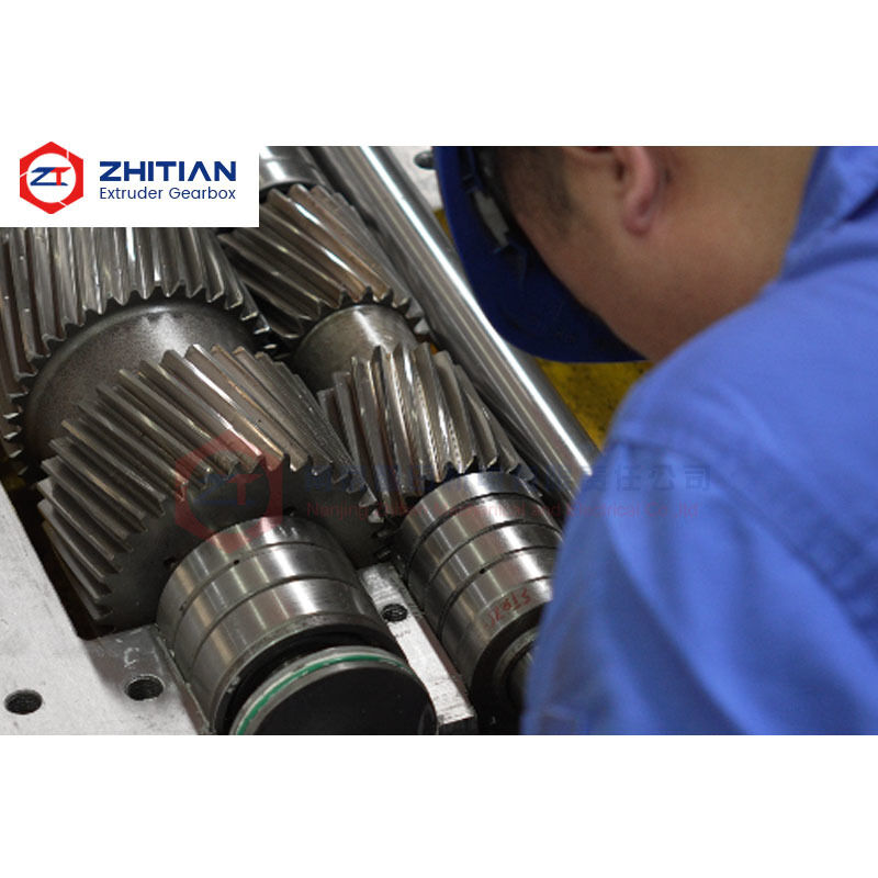
Precision-ground alloy-steel gears help maintain accurate tooth contact and stable power transmission. Gear accuracy and heat treatment are especially important during continuous high-load operation.
Bearing Support
Bearings must accommodate the combined loads generated by the closely spaced twin-output transmission system. Bearing selection and installation therefore need to be considered together with the gear and output-shaft structure.
Forced Oil Lubrication
The gearbox uses forced oil lubrication to supply lubricant to critical gear and bearing positions.
The system can incorporate filtration, pressure monitoring, temperature monitoring and oil cooling according to the gearbox configuration. Your existing product already highlights forced lubrication and external oil cooling as core configurations.
High oil temperature should not automatically be treated as a cooling problem. Excessive process load, insufficient oil flow, unsuitable lubricant, blocked filtration, bearing condition, gear contact or alignment can also increase temperature.
Replacement Accuracy Matters
Even when torque capacity is sufficient, inaccurate gearbox interfaces can cause additional loads on shafts, bearings and couplings.
For replacement manufacturing, we therefore focus on:
Center distance → Output interface → Mounting position → Shaft alignment → Lubrication connection
Gearbox inspection can include gear accuracy, shaft dimensions, output center distance, mounting interfaces, lubrication operation, leakage inspection and no-load running condition.
Maintaining these records also makes future replacement and spare-part orders easier.
Send Us 4 Parameters to Start
You do not need to prepare a complete technical specification before contacting us.
For an initial gearbox evaluation, send:
- Existing gearbox model or clear photos
- Motor power
- Required screw output speed
- Output-shaft center distance
If available, drawings, gear ratio, spline dimensions, actual motor current, operating problems and lubrication information can be provided later for detailed confirmation.
This is deliberately simpler than the current page, which asks the customer to prepare up to 14 items before evaluation.
Frequently Asked Questions
Can you replace a gearbox when the original model is no longer available?
Yes. Replacement can be evaluated from an existing gearbox model, drawing or measured machine interfaces. The center distance, shaft interfaces, mounting dimensions, speed and operating load must be confirmed.
Is motor power enough to select a twin screw extruder gearbox?
No. Motor power must be considered together with input speed, output speed, gear ratio, required torque and continuous operating load.
Why does an extruder gearbox overheat?
Possible causes include excessive operating load, insufficient oil circulation, unsuitable lubricant, blocked filtration, bearing problems, gear-mesh condition, alignment errors or inadequate cooling. The transmission and lubrication systems should be evaluated together.
Should I always choose the highest torque-density gearbox?
No. The gearbox should provide sufficient torque capacity and service margin for the actual process. Selecting a substantially higher specification than required may increase cost without solving the real operating problem.
Request a Gearbox Replacement Evaluation
If your current gearbox is overloaded, overheating, frequently failing or no longer available from the original source, send us the basic machine information first.
We can evaluate:
Required torque capacity → Gear ratio → Output speed → Center distance → Replacement interfaces → Lubrication and cooling requirements
Send Your Gearbox Data for Technical Evaluation
Start with only 4 parameters: gearbox model or photo, motor power, screw speed and center distance.


 Your message must be between 20-3,000 characters!