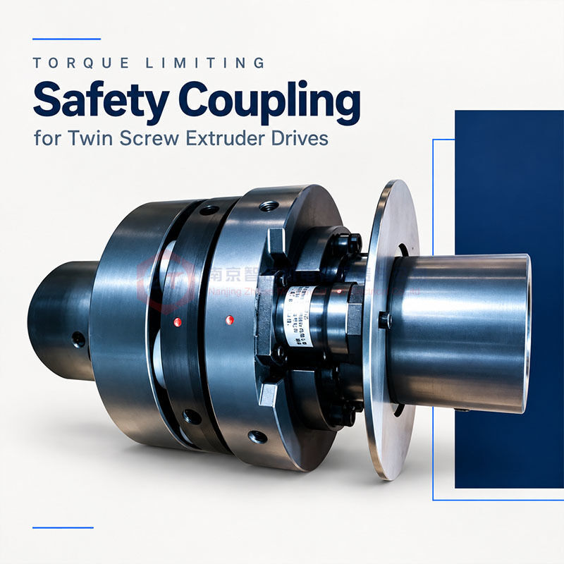
ZHITIAN supplies torque limiting safety couplings for connecting the motor and gearbox of twin screw extruders. This configuration combines a manually reset pin-type torque limiter with a pin-and-bush coupling, providing torque transmission during normal operation and full disengagement when an overload occurs.
The torque limiter uses individual safety pin modules positioned around the driving flange. Each module incorporates a steel ball at its front end that engages with a matching pocket. Imported or Chinese-made safety modules are available according to the selected configuration.
Before shipment, each torque limiter undergoes repeated forward and reverse testing on a dynamic torque test bench to verify release torque within the customer-specified range.

Modular Pin Arrangement
The safety pin modules are installed around the circumference of the driving flange. Their number is selected according to the required release torque and the capacity of the selected modules.
Common configurations use two, three, or four modules, evenly and symmetrically arranged to maintain rotational balance.
The modular construction provides access to individual pin units for servicing. Pin modules can be replaced without moving the motor or gearbox, helping simplify maintenance where repositioning the connected equipment would be inconvenient.
Replacement modules must match the confirmed assembly specification. Imported and Chinese-made modules should not be assumed to be directly interchangeable without checking their dimensions and operating characteristics.
Full Disengagement on Overload
During normal operation, the steel balls at the front of the pin modules remain seated in their corresponding pockets, allowing torque transmission between the driving and driven sides.
When the applied torque reaches the specified release threshold, the balls leave their pockets together. The driving and driven sides then fully disengage.
After release, the torque transmission path is interrupted, with no residual driving torque transmitted to the driven side. The driving side can continue to rotate independently, and the mechanism does not automatically re-engage.
Extended free running is possible within the speed, lubrication, and operating limits specified for the supplied configuration. The release setting must be matched to normal operating demand and the protection requirements of the gearbox input connection.
Bidirectional Protection Verified by Dynamic Testing
Each ZHITIAN torque limiter is tested repeatedly in both rotational directions before delivery.
Testing on a dynamic torque test bench verifies that the measured release torque remains within the range required by the customer. Repeated measurements check release consistency rather than relying only on a nominal setting.
This verification supports bidirectional overload protection and provides a practical basis for assessing release accuracy.
The required torque range and acceptance limits are confirmed with the order. Customers requiring test records or a specific numerical accuracy should state these requirements during quotation.
Optional Proximity Switch for Motor Stop Signaling
A proximity switch can be installed behind the signal plate at the rear of a pin module. When overload release occurs, movement of the signal plate allows the switch to detect the disengaged condition.
When connected to the machine control system, the switch signal can trigger a motor stop command.
Mechanical disengagement interrupts torque transmission, while the electrical signal initiates the configured stopping sequence. Actual motor stopping time depends on the drive controls, braking arrangement, and rotating inertia.
Switch position, sensing clearance, and control connections are confirmed during installation.
Manual Reset After the Overload Is Removed
The torque limiter remains disengaged until deliberately reset.
Before resetting, stop the equipment, isolate the drive against unexpected starting, and eliminate the overload cause. The rotating components must be stationary.
For this configuration, the reset sequence is:
Align the two red reference marks on the outer circumferences of the driving and driven sides so that they form a straight line.
Following the supplied instructions, use the specified hammer or reset tool to tap the designated rear reset end of each pin module.
A distinct click indicates re-engagement. Confirm that every module has returned to its specified engaged position before restarting.
Do not strike the proximity switch or signal plate. The permitted tool and tapping method should follow the instructions supplied with the coupling.
Product Specifications
| Item | Specification |
|---|
| Assembly Type | Manual-reset pin-type torque limiter with pin-and-bush coupling |
| Installation Position | Between extruder motor and gearbox |
| Module Options | Imported or Chinese-made |
| Common Module Counts | 2, 3, or 4, according to the required release torque |
| Module Arrangement | Symmetrical around the driving flange |
| Overload Response | Full disengagement |
| Protection Direction | Forward and reverse |
| Reset Method | Manual reset using alignment marks |
| Module Replacement | Without moving the motor or gearbox |
| Factory Testing | Repeated bidirectional dynamic torque testing |
Six Parameters Required for Initial Selection
| Required Parameter | Unit / Details |
|---|
| Motor Power | kW |
| Number of Motor Poles | e.g. 2, 4, 6, or 8 poles |
| Motor-Side Bore Diameter | mm |
| Motor-Side Bore Engagement Length | mm |
| Gearbox-Side Bore Diameter | mm |
| Gearbox-Side Bore Engagement Length | mm |
Bore engagement length means the shaft-to-hub fitting length on each side. For final verification, please also provide the operating speed, gearbox input limits, available installation space, and required release torque if known.
Frequently Asked Questions
Can the pin modules be replaced without moving the equipment?
Yes. Individual modules can be replaced without relocating the motor or gearbox, following the specified maintenance procedure.
Does the limiter reconnect automatically after overload?
No. It requires manual resetting after the overload cause has been removed.
Are more modules always better?
No. Module quantity and specification are selected together to achieve the required release torque and assembly configuration.
Request a Selection and Quotation
Send ZHITIAN the six selection parameters, your preferred module option, and any available connection drawings. Please indicate whether proximity-switch detection and torque test records are required.
We will confirm the configuration, release torque range, interfaces, inspection scope, and delivery schedule.


 Your message must be between 20-3,000 characters!